
- Home Page
- OZ Optics Home
- Part Number Generator
- Advanced Search
- Attenuators
- Bulkhead Receptacles/Sleeve Through Adapters
- Collimators
- Connectors/Ferrules
- Fiber Diameter Gauges
- Fibers
- Fused Couplers/Splitters
- High Power Mode Field Adapters
- High Power OZ Pen CO2 Cleaning Unit
- Laser to Fiber Couplers
- Patchcords
- PLCS Couplers/Splitters
- Test Equipment
- Laser Diode Products
- Polarization Maintaining Components
- Tapered/Lensed Fibers
- Lenses
- Accessories/Cleaning
- Bare Fiber Adapters
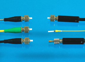
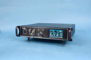
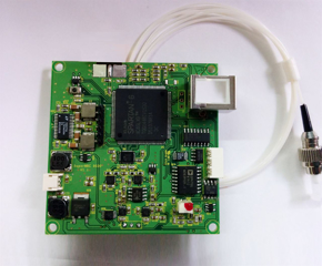
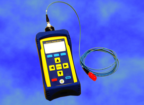
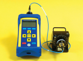
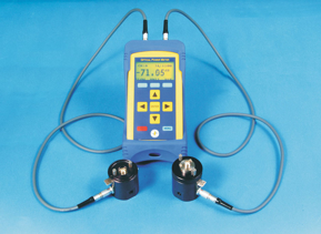
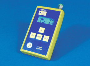
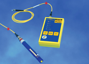



Visual Fault Locators

Features:
- High visibility (up to 6 km with a 1 mW, 635 nm source)
- Higher output up to 30 mW, non-contact style power versions available
- Continuous light or pulse modulation
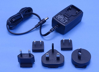
- Power supply options include alkaline batteries or AC/DC adaptor
- Carrying pouch with belt clip for pocket size version
- 1.25 mm and 2.5 mm ID universal connector receptacles available
- Pen size, pocket size, and bench top versions available
- Low battery indicator for pocket size version
- Low cost, compact, rugged, and lightweight
- 520 nm green fault locator available
- Optional built-in attenuator for controlling power output
- User selectable auto turn off mode
Applications:
- Singlemode and multimode fiber testing
- Fiber identifier applications
- Locating breaks and bends in fibers and connectors
- Identifying fibers and tracing optical signals by using modulated signals
- Optimizing splices
Product Description:
The Visible Fiber Optic Fault Locator launches 520 nm or 635 nm visible laser diode light into the fiber. When light encounters a break or sharp bend, it scatters, and the scattered light can be observed emerging from the cable. Fault locators can locate breaks in short patchcords, which an OTDR cannot detect due to their operating dead zone. A fault locator is also much less expensive than an OTDR. However, they are not recommended for use with dark-colored or armored cables.
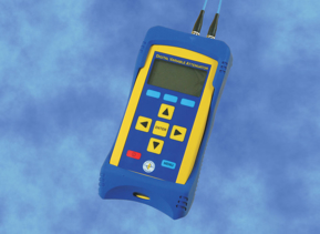
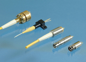
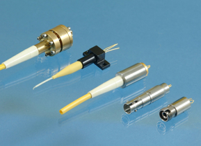
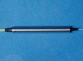
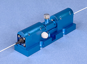
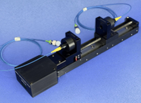
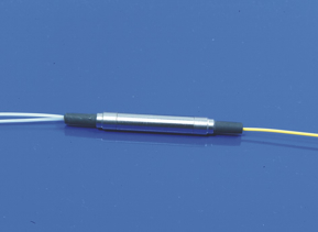
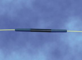
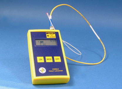
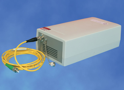
Fault locators are available in four sizes: pen size, pocket size, bench top, and a high power non-contact style bench top unit. The pocket size fault locators can be operated in either continuous wave (CW) mode or in pulse modulation mode. Pulse modulation aids in locating faults under high ambient light conditions and improves battery life. 2 Hz modulation is easy to detect by the naked eye, while 270 Hz and 2 kHz pulse modulation modes are used for fiber identification by detectors. The pocket size fault locator comes with a carrying pouch and belt clip. Pen size fault locators are CW and 2 Hz modulation internally, as are high power bench top units, including the non-contact version.
Another use for fault locators is to check connector quality. Often a connector may appear to be perfect, even when viewed with a microscope, but inside the connector ferrule itself, poor gluing or dirt may create a microbend in the fiber. This microbend will produce excess insertion losses or return losses, and may result in premature failure of the connector. If one launches visible light through the fiber, so that it emerges from the connector in question, one can readily see the distortion as a series of rings superimposed on a normal output (See Figure 1). Bending or twisting the fiber may affect the overall intensity pattern, but not the ring pattern itself.
One of the key advantages of OZ Optics' pocket size and bench top model fault locators is that they use singlemode fiber for 633 nm, which has a four micron diameter core instead of a nine micron diameter core. This reduces any potential misalignment errors between the connector on the fault locator and the connector on the fiber. It also ensures that the light launched into the cable being tested matches the fundamental mode as much as possible. The light coming out of the other end will tend to look circular and Gaussian, rather than showing several modes. This makes it easier to identify microbends in connectors.





Visual Fault Locators
Filter by:
Clear All